Executive order
D-186-8
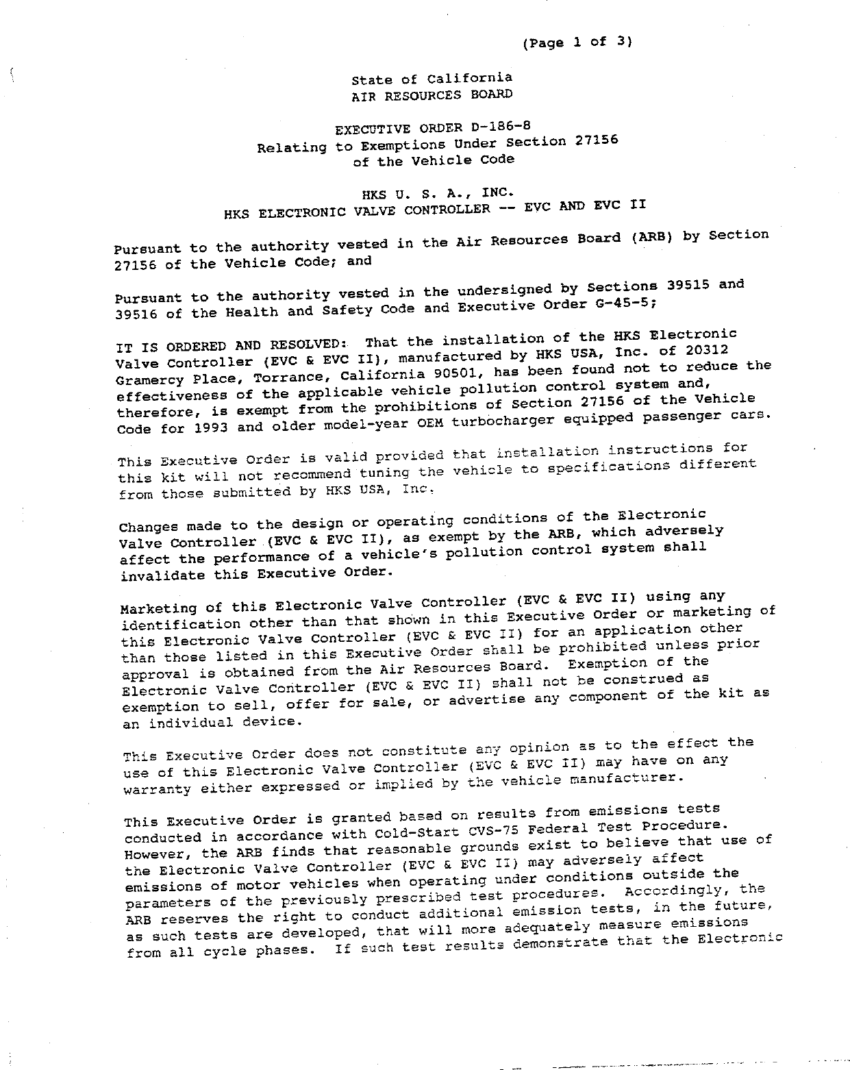
HKS USA, Inc.
Vehicle applications
No vehicle applications were preserved for this order.
Part records
| Part number | Model/specification | Modification | Remarks |
|---|---|---|---|
| 1993 and older model-year passenger cars with OEM turbochargers |
Executive order
HKS USA, Inc.
No vehicle applications were preserved for this order.
| Part number | Model/specification | Modification | Remarks |
|---|---|---|---|
| 1993 and older model-year passenger cars with OEM turbochargers |