Executive order
D-133-6
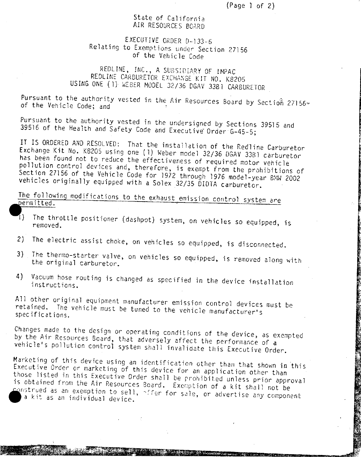
Redline, Inc.
Vehicle applications
No vehicle applications were preserved for this order.
Part records
| Part number | Model/specification | Modification | Remarks |
|---|---|---|---|
| 32/36 DGAV 33B1 | 1972-1976 BMW 2002 vehicles originally equipped with Solex 32/35 DIDTA carburetor | Throttle positioner is removed, electric assist choke is disconnected, and thermo-starter valve is removed, vacuum hose routing is changed. |