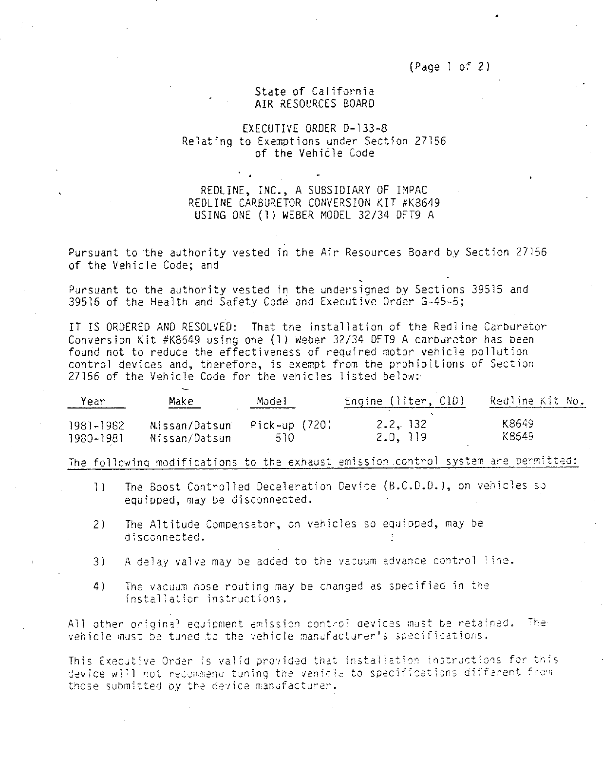
Approval Details

Valid E.O.

Validity

This Executive Order approved the specified parts on on May 27, 1986.
As of Tuesday, February 4th, 2025 this Executive Order has not been overturned or superceeded.

Approved Parts

Part NumberModelsModification
32/34 DFT9 A1980-1981 Datsun 510 2.0L 1981-1982 Datsun 720 Pick-Up 2.2LBCDD and altitude compensator disconnected, and delay valve added to vacuum advance control line, vacuum hose routing changed

This Executive Order may be listed as:
  • C.A.R.B.E.O. D-133-8
  • Executive Order 133-8 / D133-8
  • ARB # D-133-8
  • Executive Order No: D-133-8
  • C.A.R.B. No. D-133-8
  • Resolution D-133-8
For Free CARB Executive Order Status verification, email an image of the device Executive Order label as well as the Year/Make/Model and Test Group # of the vehicle to [email protected]

Download: Executive Order D-133-8 PDF

D-133-8 Document:


CARB_D-133-8

                                                                (Page 1 of 2)

                                     State of California
                                     AIR RESOURCES BOARD

                                    EXECUTIVE ORDER D—133—8
                     Relating to Exemptions under Section 27156
                                 of the Vehi¢le Code


                        REDLINE, INC., A SUSSIDIARY OF IMPAC
                      REDLINE CARBURETOR CONVERSION KIT #K8649
                       USsING ONE (1) wEBER MODEL 32/34 DFT9 A


Pursuant to the authority vested in the Air Resources Board by Section 27156
of the Vehicle Code; and

Pursuant to the authority vested in the undersggned by Sections 39515 and
39516 of the Health and Safety Code and Executive Order G—45—5;

IT IS ORDERED AND RESOLVED:  That the installation of the Redline Carburetor
Conversion Kit #K8549 using one (1) wWeber 32/34 DFT9 A carburetor has been
found not to reduce the effectiveness of required motor vehicle pollution
control devices and, therefore, is exempt from the prohibitions of Section
27156 of the Vehicle Code for the vehicles listed belowr

  Year             Make         _     _Model         Engine (liter, CID)        Redline Kit No.

1981—1982       Nissan/Datsun        Pick—up (720)         2.2, 132               K8649
1980—1981       Nissan/Datsun            510               2.0, 119        —      K8649
The following modifications to the exhaust emission control system are permitted:


                                                                                          ib
    11      The Boost Controlled Deceleration Device (B.C.0.D.), on vehicles so
            equipped, may be disconnected.

    2)       The Altitude Compensator, on vehicles so equippad, may be
            disconnected.                              i

    3)      A delay valve may be added to the vacuum advance control           line.

    41      The vacuum hose routing may be changed as specified in the
            installation instructions.

All other original equipment emission control aeviecss m
venicle must be tuned to the vehicle manufacturer‘s specifi

This Execuative Order is valid provided |
device will not recommend tuning the venicle
those submitted oy the    vice manafacturer.


 REDLINE, INC.                                         EXECUTIVE ORDER D—133—8
                 >                                     (Page 2 of 2)


 Changes made to the design or operating conditions of the device, as exempted
 by the Air Resources Board, that adversely affect the performance of a
 vehicle‘s poliution control system shall invalidate this Executive Order.

  Marketing of this device using an identification other than that shown in this
° Executive Order or marketing of this device for an application other than
  those listed in this Executive Order shall be prohibited unless prior approval
  is obtained from the Air Resources Board. Exemption of a kit shall not be
  construed as an exemption to sell, offer for sale, or advertise any component
  of a kit as an individual device.

 This Executive Order does not constitute any opinion as to the effect that the
 use of this device may have on any warranty either expressed or implied by the
 vehicle manufacturer.

 THIS EXECUTIVE ORDER DOES NOT CONSTITUTE A CERTIFICATION, ACCREDITATION,
 APPROVAL, OR ANY OTHER TYPE OF ENDORSEMENT BY THE AIR RESOURCES BOARD OF ANY
 CLAIMS OF THE APPLICANT CONCERNING ANTI—POLLUTION BENEFITS OR ANY ALLEGED
 BENEFITS OF THE REDLINE CARSURETOR CONVERSION KIT #K8649.

 No claim of any kind, such as "Approved by Air Resources Soard" may be made
 with respect to the action taken herein in any advertising or other oral or
 written communication.

 Section 17500 of the Business and Professions Code makes untrue or misleading
 advertising unlawful, and Section 17534 makes violation punishable as a
 misdemeanor.

 Section 43644 of the Health and Safety Code provides as follows:

     "43644.   ({a} No person shall install, sell, offer for sale, or advertise,
     or, except in an application to the state board.for certification of a
     device, represent, any device as a motor vehicle pollution control device
     for use on any used motor vehicle unless that davice has been certified by
     the state board. No person shall sell, offer for sale, advertise, or
     represent any motor vehicle pollution control device as a certified device
     which, in fact, is not a certified device.   Any violation of this
     subdivision is a misdameanor."

 Any apparent violation of the conditions of this Executive Order will be
 submitted to the Attorney General of California for such action as he deems
 advisable.            j

                                                   14 "
                          .     .     .     r‘)   +9               snor
 Executed at El Monte, California, this     _/       day of May,   1986.

                                            70    al oldifya 1iz
                                          // L/4j ACET i\
                                          K. D. Orachand, Chief
                                          Mobile Source Division


               State of California
               AIR RESOURCES BOARD


EVALUATION OF THE REDLINE CARBURETOR CONVERSION KIT
        NO. K8649 USING ONE (1) 32/34 DFT9 A
      WEBER CARBURETOR FOR EXEMPTION FROM THE
    PROHIBITIONS OF VEKICLE CODE SECTION 27156
     IN ACCORDANCE WITH SECTION 2222, TITLE 13
       OF THE CALIFORNIA ADMINISTRATIVE CODE


                       MAY, 1986


               EVALUATION OF THE REDLINE CARBURETOR CONVERSION
               KIT NO. K8649 USING ONE (1) MODEL 32/34 DFT9 A
                    WEBER CARBURETOR FOR EXEMPTION FROM THE
                  PROHIBITIONS OF VEKICLE CODE SECTION 27156
                   IN ACCORDANCE WITH SECTION 2222, TITLE 13
                     OF THE CALIFORNIA ADMINISTRATIVE CODE


                                      by
                            Mobile Source Division
                              State of California
                             AIR RESOURCES BOARD
                             9528 Telstar Avenue
                             E1 Monte, CA   91731


(This report has been reviewed by the staff of the California Air Resources
Board and approved for publication. Approval does not signify that the
contents necessarily reflect the views and policies of the Air Resources
Board, nor does mention of trade names or commercial products constitute
endorsement or recommendation for use.)


                                        SUMMARY


      Redline, Inc., a distributor of Italian made Weber carburetors, has

applied for exemption from the prohibitions of Vehicle Code Section 27156 for

the Redline Carburetor Conversion Kit No. K8649 using one (1) Weber model

32/34 DFT9 A carburetor.

      The Redline Carburetor Conversion Kit is designed to replace the Hitachi

carburetors found on 1981—1982 Nissan/Datsun pick—up trucks and 1980—1981

Nissan/Datsun 510 passenger cars with 2.0 or 2.2 liter engines.

      Comparative exhaust emission tests and other information submitted

demonstrate that the aftermarket Redline Carburetor Conversion Kit No. K8649

using one (1) Weber model 32/34 DFT9 A carburetor does not adversely affect

emissions of the applicable vehicles.      Based on the results of the tests and

the evaluation of the Redline Carburetor Conversion Kit, the staff recommends

that the exemption be granted as requested for the following vehicle

applications:


   Year         Make            Model      Engine {liter, CID)     Redline Kit No.


1981—1982       Nissan/Datsun   Pick—up           2.2, 132             K8649

1980—1981       Nissan/Datsun   510               2.0, 119             K8649


                                         CONTENTS


                                                    Page Number


SUMMARY

CONTENTS                                                  11.

1.     INTRUODUCTION

II.    CONCLUSION

III.   RECOMMENDATION

IV.    DEVICE DESCRIPTION

V.     DEVICE EVALUATION

VI.    DISCUSSION


APPENDIX

       OEM Carburetor Diagrams                          A—1

       Weber 32/34 DFTY A                               A—2

       Installation Instructions:        K8649           A—3

       Underhood Label

       Carburetor Calibrations:     K8649                A—5

       ldentificaion Labels:     K8649                  A—6


EVALUATION OF THE REDLINE CARBURETOR CONVERSION KIT NO. K8649 USING ONE (1)
MODEL 32/34 DFT9 A WEBER CARBURETOR FOR EXEMPTION FROM THE PROKIBITIONS OF
VEHICLE CODE SECTION 27156 IN ACCORDANCE wITH SECTION 2222, TITLE 13 OF THE
CALIFORNIA ADMINISTRATIVE CODE


I.       INTRODUCTION

         Redline, Inc. of Compton, California, a subsidiary of Imported Parts and

Accessories Corporation (IMPAC), is a distributor of Italian made Weber

carburetors.     The company has applied for exemption from the prohibitions of

Vehicle Code Section 27156 for a Carburetor Conversion Kit designated as

Redline Kit No. K8649 using one (1) Weber model 32/34 DFT9 A carburetor to

replace the original equipment manufacturer (OEM) Hitachi two—barrel

carburetors found on the following vehicles:


      Year      Make             Mode]     Engine (liter, CID)    Redline Kit No.


1981—1982       Nissan/Datsun    Pick—up         2.2, 132            K8649

1980—1981       Nissan/Datsun   510              2.0, 119            K8649


         This report describes the evaluation of the Redline Carburetor

Conversion Kit and the findings.

II.      CONCLUSION

         Comparative exhaust emission data and other information submitted by the

applicant demonstrated that the Redline Kit No. K8649 using one (1) 32/34

DFT9 A Weber carburetor meets the Air Resources Board (ARB) requirements for

exemption from the prohibitions of Vehicle Code Section 27156.


III.   RECOMMENDATION

       Based on the submitted information and the emissions test data on the

Redline Carburetor Conversion Kit, the staff recommends that Redline, Inc. be

granted exemption from the prohibitions of Vehicle Code Section 27156 for the

Redline Carburetor Conversion Kit No. K8649 for use on the vehicles described

above and that Executive Order No. D—133—8 be issued.

I¥.    DEVICE DESCRIPTION

       The Redline Carburetor Convérsion Kit No. K8649 uses one (1) model 32/34

DFT9 A Weber carburetor as an economical replacement for the OEM carburetors

found on the 1980—82 Nissan/Datsun pick—up trucks and 510 passenger cars

described previously.

       These vehicles are equipped with Hitachi model DCR 360 or DCR 342

carburetors depending on the model—year.   All these OEM carburetors are of the

progressive two—barrel design (See Appendix 1).

       The Weber 32/34 DFTQ A is a progressive two—barre!l carburetor which is

similar in basic design to the OEM carburetors (See Appendix 2).    The Weber

32/34 DFT9 A is a slightly different version of the Weber DFT (Ford 740)

carburetors used as original equipment on some Ford imports orignally sold in

California.   It has provisions for vacuum operated emission control systems,

including distributor vacuum advance/retard units, EGR and air injection

control systems.

       A variety of emission control devices are used on these vehicles.   Some

are integral to the OEM carburetor and others are external devices which

either control specific functions of the OEM carburetor or are activated by

movement of the throttle.   The installation of the Weber carburetor retains

most of these devices or duplicates the functions of the devices in a


different manner, however, some devices cannot be retained.      These devices and

their disposition after the installation of the Weber carburetor are:

        1)   The Boost Controlled Deceleration Device (B.C.D.D.}, on vehicles so

             equipped, may be disconnected.

        2)   The Altitude Compensator, on vehicles so equipped, may be

             disconnected.

        3)   A delay valve may be added to the vacuum advance control line.

        4)   The vacuum hose routing may be changed as specified in the

             installation instructions.

        The Redline Kit No. K8649 comes complete with a Weber DFT9 A carburetor,

an air cleaner adaptor and all the hoses, gaskets and hardware necessary to

install the Weber carburetor on the Nissan/Datsun pick—ups or 510 passenger

cars.    Installation instructiohs, which are included in every kit, show the

kit installer how to properly install the Weber carburetor.      Vacuum hose

routing diagrams, contained in the instructions, show the proper vacuum hose

connections to the Weber carburetor (see Appendix 3).      An underhood 1abe1;

included in the kit, is to be affixed to the vehicle near the OEM vacuum hose

routing diagram which states that the vehicle is equipped with a Redline Kit

and that appropriate vacuum hose routing diagrams may be found in the

applicable Redline Kit installation instructions.      For persons who may have

technical questions or need a copy of a vacuum hose routing diagram, the

Redline technical information phone numbers (Tech Lines) are included on this

label   (see Appendix 4).    The carburetor calibration for kit No. K8649 is shown

in Appendix 5.    A facsimile of the identification label is shown in Appendix 6.

v.      DEVICE EVALUATION

        The applicant performed comparative cold—start CVS—75 exhaust emission

tests at Import Certification Laboratories in Anaheim, California.      A 1982


Nissan/Datsun pick—up truck with a 2.2 liter engine and an automatic

transmission was used as the test vehicle.         The 1982 model—year vehicle was

used for testing since vehicles of 1982 model—year were required to meet more

stringent emission standards than vehicles of the previous model—years.          It

would be expected that vehicles of previous model—years would have the same

degree of performance/emissions impact as the vehicle tested when using the

same Redline Kit.

      The results of the submitted data are shown in Table 1.

                                         Table 1

                                   Exhaust Emissions gm/mi        Fuel Economy
    Condition                HC           CO             NOx      City —mi/gal

    Baseline                0.50         17.58          0.54           22.54

    Redline Kit             0.43         19.18          0.44           18.18

      VI.      DISCUSSION

      The Redline carburetor conversion kit No. K8649 uses a model 32134 DFT

Weber carburetor.     Since this Weber carburetor had been evaluated for the

exemption of other Redline kits with similar design, no confirmatory tests

were performed.     The submitted comparative test data and other information

submitted by the applicant were used for the evaluation.

      The results of the emission testing show no increase in HC or NOx

emissions.     The differences in CO emissions between the baseline and device

tests are considered to be within the limits of test variability as determined

by the Haagen—Smit Laboratory.

      This demonstrates that the installation of the Redline Kit. No. K8649

and the modifications to the original exhaust emission control system required

for the installation will not have an adverse effect on emissions from the 1982


Nissan/Datsun pick—up test vehicle which was selected to be representative of

all the vehicies on this exemption application.   It would be expected that the

conversion kit No. K8649 would achieve the same level of emission control when

installed on the same type of vehicles to replace OEM carburetors of similar

designs.

      Redline has submitted all the required information and fulfilled the

requirements for an exemption.


                                  INSTALLATION INSTRUCTIONS
 READ & UNDERSTAND ALL STEPS OF THESE INSTRUCTIONS :BE—F;ORE
 BEGINNING THIS INSTALLATION. AFTER UNPACKING, EXAMINE THE
 CARBURETOR AND OTHER COMPONENTS FOR SHIPPING DAMAGE.
 THESE INSTRUCTIONS SHOULD BE RETAINED WITH VEHICLE RECORDS
 AFTER INSTALLATION OF THIS KIT FOR SMOG INSPECTION PURPOSES.

                                                DATSUN
                                               1980—81 510
                                               1981—82 720
                                        222 ENGINES (All Trans.)
                                     FOR KIT NO‘S K8e4g, 52—50508
                                     USING (1) WEBER 32/34 DFT—9A
                  TOOLS AND EQUIPMENT                                           PARTS SUPPLIED WITH                           &
                         NEEDED                                                   INSTALLATION KIT:

                                                                          1 — Weber 32/34 DFT—9A Carb.
             Combination,    box or open—end wrench                             o e
             ({metric)    box or op         wrencnes                      1 — Air Filter Adaptor                              i
             Socket Set (metric}                                          1 — Wire Assembly                                    :
             Screwdrivers (regular and Phillips)                                            §
             Pliers                 Gasket Scraper                        1 — Hardware Kit
             Wiping Rags            Cleaning Soivent                     NOTE: A new fuelfilter should                         :
             Knife                  Gasket Sealer                        be installed with this kit.                          i3

                                             TUNE—UP SPECIFICATIONS
All tung—up specifications for the Weber Carburetor remain the same as those specified by the
Factory for the original unit. Emissions tune—up should be carried out by a suitably qualified Dealer
or Independent garage, using infrared gas and analyzing equipment.

NOTE: Late model vehicles fitted with Emission Control Systems have many vacuum lines and
electrical connections in the fuel systems. it is essential when dismantling, that disconnected lines
should be identified with a corresponding number tag or label system. To establish function, locate
and identify the source of each line. Use the under hood emissions diagram, or a factory service
manual for reference when identifying hoses. (Modified vacuum diagrams showing the Weber
installation are provided in these instructions)


___________________                                            4. Disconnect all vacuum hoses & tubes from the
                                                                  air filter. Identify removed lines to aid in reas—
. Remove the vehicle gas cap.                                     sembly. (FIG. 1)

. Disconnect the battery.                                      5. Remove the air filter from the vehicle.

. Remove the two air filter bracket boits on top               6. Disconnect all carburetor vacuum lines and
  of the cam cover and wing nut on center of air                  wires. Identify removed lines and wires to aid in
  filter.                                                         reassembly. (FIG. 2)

 This is soid under the provisions of California Air Resources Board Executive Order No. D—133—8 (C.A.R.B. E.0. No. D—133—8
 Products with C.AR.B. E.0. numbers are exempt from the prohibitions of Section 27156 of the California Vehicie Code.
 Performance kits so noted are legal for use on public highways in California.
WEBER DISTRIBUTION


      {NCTE:) Some vehicles have altitude compen—
      sation devices which have three (3) vacuum lines
      connecting the carburetor with a unit mounted on
      the right inner fender, behind the Boost control
      unit. The altitude compensator will not be used
      with this conversion and may be disconnected
      and removed. All vacuum sources should be
      capped off. (FIGS. 5 & 6)

  . Remove the fuel line and clamps.

  . Remove throttle cable from the cable quadrant.
    (Note: It is not necessary to remove throttle cable
    bracket from manifold.)

  . Remove carburetor flange nuts. Lift off carburetor
    and spacer from the intake manifold. Insert a clean
    rag in the intake manifold port and thoroughly
    clean the carburetor mounting surface of all dirt
    and gasket debris.

      KIT INSTALLATION                                         A. Anti—Backfire Vaive Hose
                                                               B. Cam Cover Vent
                                                               C. Hot Air Tube
10. Remove the rags from the intake port and install the
                                                               D. Manifold Vacuum
      manifold gasket (the one with throttle bore holes        E. Air Induction Pipes
      closer together) on manifold.                            F. Thermal Vacuum Valve/Ait. Compensator
       (FIG.3)

11. Install the 3/8 spacer supplied (O.E. spacer is not
    reused) with the tappered holes matching the
      intake manifold and the throttle bores on Weber                                                 FIG,
      Carburetor. (FIG. 3)                       ’

12. Install carburetor gasket (the one with throttle bore
      holes farther apart) on heat spacer.
      (FIG. 3)

13. Install Weber carburetor with the choke assembly
    toward the front of vehicle.

14.   Secure the carburetor with the flange nuts and
      washers supplied in the kit.

15. Reconnect throttle cable. Adjust the throttle cable
    tension to factory spacifications, or until desired
    accelerator pedal tension is achieved.

16. Locate and identify the "positive" 12 volt wires that
      led to the original idle cut off solenoid and electric
      choke. Using the female connectors and wires
      supplied in the kit, connect the Weber idle cut—off
      solenoid and electric choke to their respective
      wires on the original loom. Use the shrink tubing
      supplied to insulate each connection.                    A. EGR Port
                                                               B. Vacuum Advance to Distributor
17. Connect the fuel hose, supplied in the kit, from the       C. Boost Control Unit Line                 .
      stock fuel inlet on Weber Carburetor. Secure with        D. Electrical Connector
                                                               E. Throttle Cable
      clamps supplied. Note: It may be necessary to
                                                               F. Venturi Vacuum
      bend stock fuel outlet slightly towards the rear of      G. High Alt. Compensator
      vehicle to clear Weber throttle lever. Make sure to      H. Fual Outiet
      check this for wide open throttle situations.


 18. ALL VEHICLES: Cut the stock        distributor
     vacuum advance hose approximately 2—3" from
     the vacuum advance diaphragm on the
     distributor. Insert the vacuum delay valve from the
     kit with the Gold side facing the distributor.
     (FIGS. 4 & 5)

 19. ALL VEHICLES: Connect the V.V.T, Valve va—
     cuum    hose to the venturi vacuum port on the We—
     ber carburetor. (FIGS. 4, 5 & 6)

 20. 1980 MODEL 510, ‘81—82 MODEL 720:
     Connect the EGR control vaive vacuum hose to
     the EGR port on the Weber carburetor.
     {FIGS 4 & 5)

 21. 1981 MODEL 510 ONLY: Cut the hose for the
     EGR vacuum control valve and install one of the
     vacuum tees from the kit. Cut a 2" piece of
     vacuum hose (supplied in kit) and install it on the
     Weber Carburetor EGR port. Connect                   the
     remaining end of the hose to the tee.
     (FIGS. 4 & 6)
22. 1980     MODEL       510,    ‘81—"82     MODEL       720:
     Connect the distributor vacuum advance hose to
     the vacuum advance port on the Weber Car—
     burator. (FIGS. 4 & 5)

   . 1981    MODEL      510     ONLY:      Using   the   tees
     supplied in the kit tee together the distributor
     vacuum advance hose and the No. 1 EGR vaive
     hose as shown in FIG. 6. Connect the remaining
     end of the distributor vacuum advance hose to
                                                                           Front of
     the    vacuum     advance    port     on   the   Weber                Vehicle
     carburetor.
     (figs. 4 & 6)

24. Using the rubber plugs provided in the kit, cap off
     the vacuum tees leading to the altitude com—
     pensator and Boost Control Unit as shown in                Intake
     FiGS. 5 & 6.                                               Manifold

25 Install the air filter adaptor with the allen bolts and
    gasket supplied.

26. Install the original air filter removed in Step 5 with
    the spacers and boits supplied in kit.

27. Reconnect the vacuum lines and tubes to the air
    filter assembly. NOTE: The stock hot air tube
    from the heat riser and the air suction tubes are of
    sufficient length; however, they may require some
    reshaping to ensure that they will stay in place
    when installed.

    Reconnect vehicle battery. Reinstall the gas cap.

29. Depress the throttle fully, then release to initiate
    the cold—start device.


30. START THE ENGINE. After warm—up, check
    for leaks around the carburator mounting base
    and correct as needed.
                                                               WEBER MODEL DFT FAST IDLE ADJUST—
31. Adjust idle speed, fast idle and idle mixture to           MENT: With the engine warmed up and Off,.
   factory specifications.
                                                               open the throttle and manually engage the
                                                               choke by closing the choke plates (butterflies).
32. CHECK FOR ADEQUATE HOOD CLEAR—                             Release the throttle then the choke plates. The
    ANCE BEFORE CLOSING THE HOOD.                              fast idle cam should be activated and the fast
   If after following these instructions, you                  idle speed screw should be positioned on the
   require further    assistance, please call                  cam      shoulder.      Start   the   engine      Do   not
   the   Weber     Tech.     Service    Dept.   at   the       depress the throttle pedal or choke will
   phone       numbers       listed    below,   during         become inoperative. To adjust the fast idie
   normal business hours.                                      speed, loosen the locknut and turn the fast idie
                                                               screw in (clockwise) to increase speed and out
         1—800—WEBER US (Outside CA)                           {counter clockwise) to decrease speed. Once
                (932—3787)                                     fast idle speed is set, tighten the locknut in
                                                               place.
         1—800—WEBER CA (CA only)
              (932—3722)


   UNIVERSAL DFT
   WITH VACUUM PORTS IDENTIFIED
                                                                                                     Locknut


                                                                                                                 Fast—idle
                                                                                                         T       Adj. Screw


                                                                                           Venturi Vacuum Port


                                                                                   Vacuum Advance Port


                                                           Idie Cut—Off Solenold


                                                EGR Port


                                                                                                             FIG. 4


                                                    ‘80 DATSUN 510
                                             ‘81—82 DATSUN 720 (Cal, only)
              ALL DEVICES SHADED SHOULD BE DISCONNECTED AND REMOVED

                                                        BOOST                    ALTITUDE
                       vACUUM                        CONTROL UNIT              COMPENSATOR
                       SWITCH                                   C
                                                                          To AIR
                                                                   SAP   CLEANER wesen
                             caP                                 Z—___—*~~
                                                                eBz              EGR                   PoRT
              WEBER VACUUM
              ADVANCE PORT


                                                                                              WeeeR veNtTugRl
                                                                                        A~,     VACUUM PORT


                                                                                              \, EGR CONTROL
                         d                                                                             VALVE
                                              i{  THERMAL _
                                              [ vacuum vatve!                 SENSOR           ):
                                               |                                               — cen tuBE

                  DistRiBUTOR                ts
                                                                                                    CATALYST

                                                               weser vacuum         <<4____[i_?
                                                          I     DELAYVALVE
                  CANISTER                   FROM                 (Gold side                                                 FIG. 5
                               FUEL TANK                           toward Dist.)

                                              ‘81 DATSUN 510 (Cal. only)
              ALL DEVICES SHADED SHOULD BE DISCONNECTED AND REMOVED


                                                                            Feltd
                                                                       COMPENSATOR

                                                         ;9;/                          wEesenr
                             cap              flF i             _ CAP                EGR PORT

                                                                                              WEBER VENTURI
                                                    rrrmaade           T     ;E_--—"          VACUUM PORT
               VXSEAE\:C‘!EASS% a
                                   Provel)         en          /                               NO. 2 EGR vALVE
                                                                           i(G)Lt—             no.1 Een vaLve
                                                                                        1             VVT vALVE

                                                   THERMAL
                                              VACUUM VALV
                                                       VALVE                                        EGR VACUUM
                                                                                              CONTROL VALVE


                                                        WEBER VACUUM
                                                         DELAY VALVE
                                                           (Gold side
                                                          toward dist.)

                                                                                                                           FIG. 6

WEBER DISTRIBUTION                                                   6/86                                         445.8649—1IN


Document Created: 2005-09-01 12:42:25
Document Modified: 2005-09-01 12:42:25

Previous E.O. D-133-7 | Previous E.O. D-132 | Next E.O. D-133-9 | Next E.O. D-134