Executive order
D-246-1
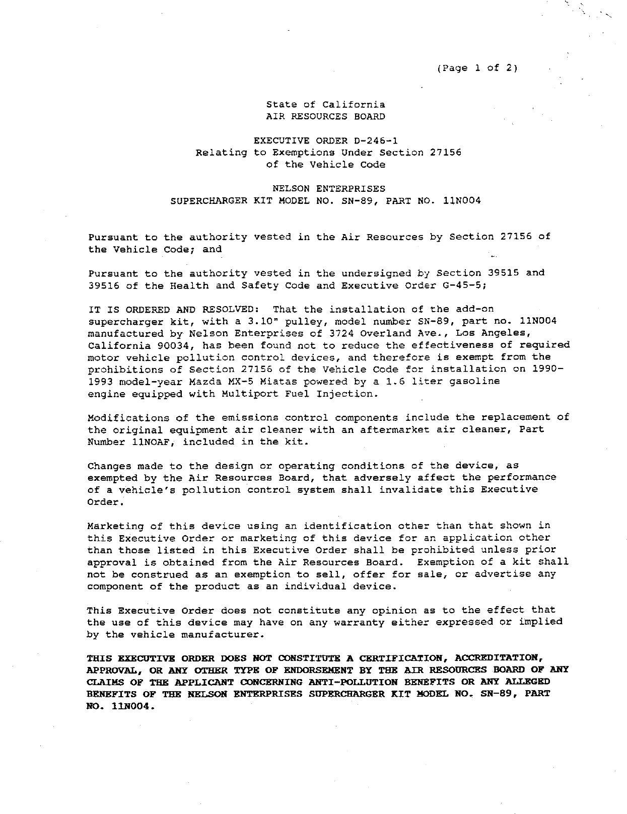
Nelson Enterprises
Vehicle applications
No vehicle applications were preserved for this order.
Part records
| Part number | Model/specification | Modification | Remarks |
|---|---|---|---|
| 11N004 | 1990-1993 Mazda MX-5 Miatas powered by a 1.6L gasoline engine equipped with Multiport Fuel Injection |