Executive order
D-27
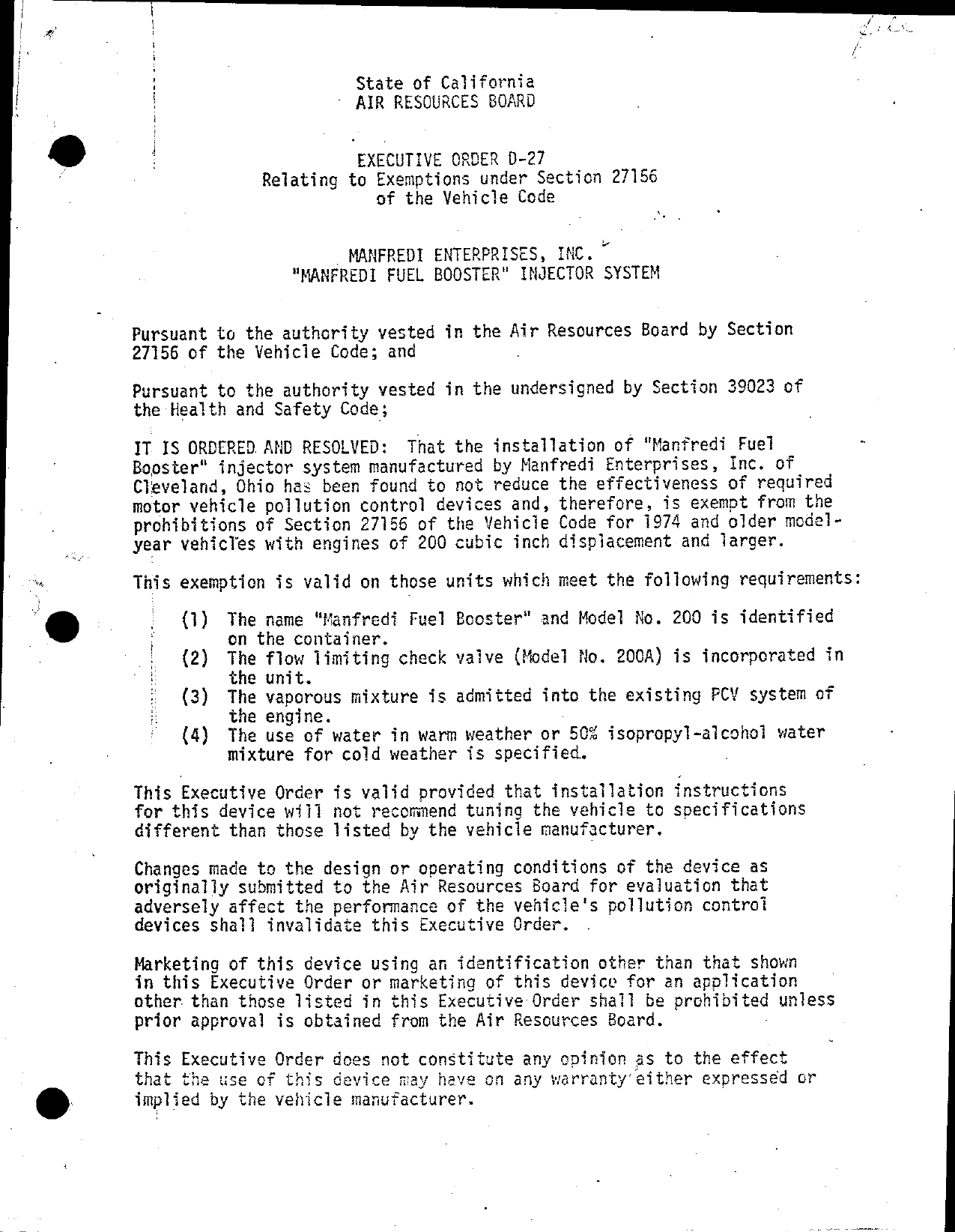
Manfredi Enterprises, Inc.
Vehicle applications
No vehicle applications were preserved for this order.
Part records
| Part number | Model/specification | Modification | Remarks |
|---|---|---|---|
| 200 | 1974 and older vehicles with engines 200 CID or larger engines |