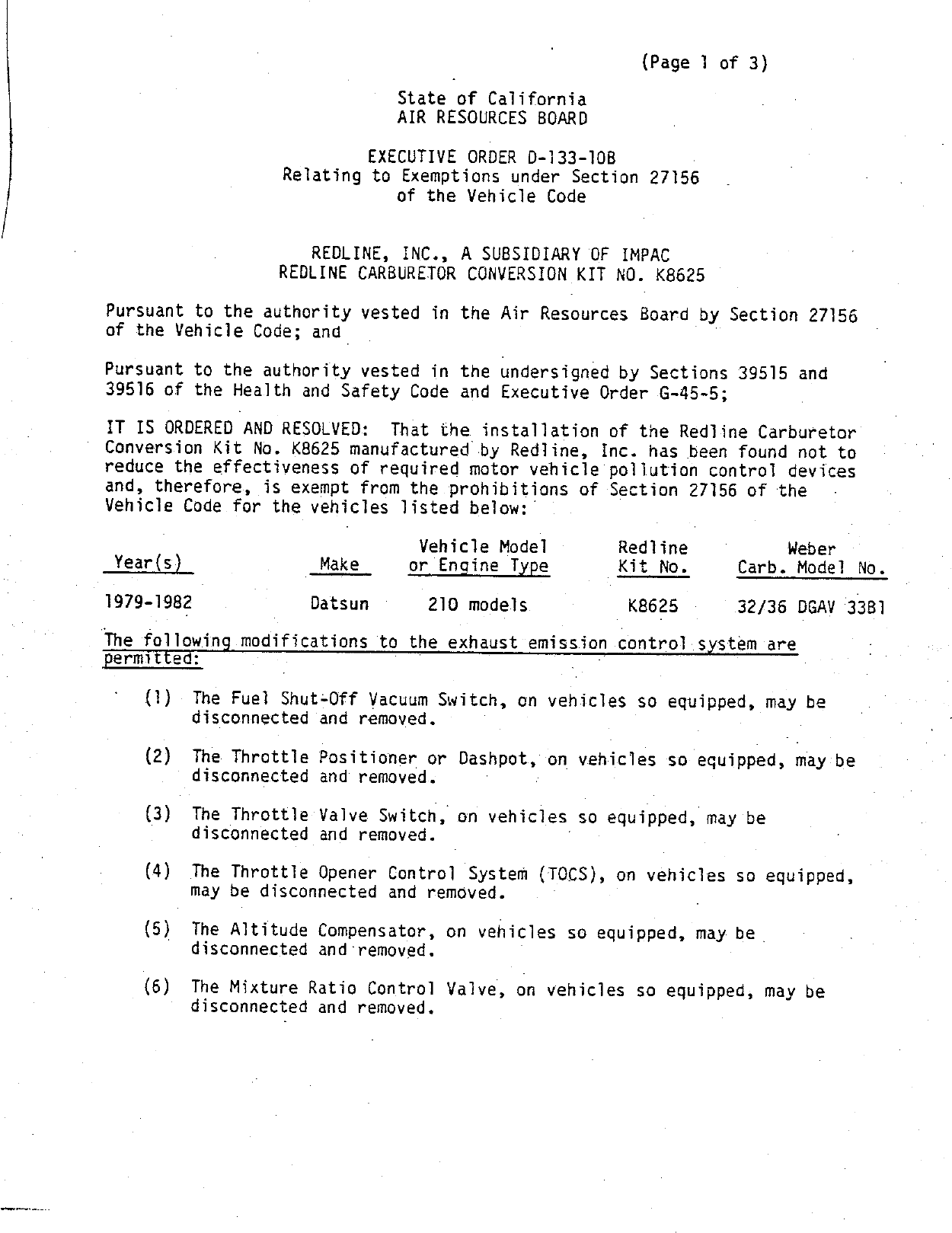
Approval Details

Valid E.O.

Validity

This Executive Order approved the specified parts on on August 5, 1986.
As of Tuesday, February 4th, 2025 this Executive Order has not been overturned or superceeded.

Approved Parts

Part NumberModelsModification
32/36 DGAV 33B11979-1982 Datsun 210The fuel shut-off vacuum switch, throttle positioner or dashpot, throttle valve switch, throttle opener control system, altitude compensator, and mixture ratio control valve may be disconnected or removed.

This Executive Order may be listed as:
  • C.A.R.B.E.O. D-133-10B
  • Executive Order 133-10B / D133-10B
  • ARB # D-133-10B
  • Executive Order No: D-133-10B
  • C.A.R.B. No. D-133-10B
  • Resolution D-133-10B
For Free CARB Executive Order Status verification, email an image of the device Executive Order label as well as the Year/Make/Model and Test Group # of the vehicle to [email protected]

Download: Executive Order D-133-10B PDF

D-133-10B Document:


CARB_D-133-10B

                                                              (Page 1 of 3)

                                  State of California
                                  AIR RESOURCES BOARD

                                EXECUTIVE ORDER D—133—108
                    Relating to Exemptions under Section 27156
                                of the Vehicle Code


                       REDLINE, INC., A SUBSIDIARY OF IMPAC
                    REDLINE CARBURETOR CONVERSION KIT NO. K8625

Pursuant to the authority vested in the Air Resources Board by Section 27156
of the Vehicle Code; and .

Pursuant to the authority vested in the findersigned by Sections 39515 and
39516 of the Health and Safety Code and Executive Order G—45—5;

IT IS ORDERED AND RESOLVED:        That the installation of the Redline Carburetor
Conversion Kit No. K8625 manufactured by Redline, Inc. has been found not to
reduce the effectiveness of required motor vehicle pollution control devices
and, therefore, is exempt from the prohibitions of Section 27156 of the
Vehicle Code for the vehicles listed below:

                                     Vehicle Model          Redline          Weber
 Year(s})                Make       or Engine Type          Kit No.     Carb. Model No.

1979—1982               Datsun        210 models             K8625      32/36 DGAV 3381

The following modifications to the exhaust emlss1on control system are
permitted:

    {1)     The Fuel Shut—Off Vacuum Switch, on vehicles so equipped, may be
            disconnected and removed.

     {(2)   The Throttle Positioner or Dashpot, on vehicles so equipped, may be
            disconnected and removed.          :

     {(3)   The Throttle Valve Switch, on vehicles so equipped, \may be
            disconnected and removed.

     (4)    The Throttle Opener Control System (TOCS), on vehicles so equipped,
            may be disconnected and removed.

     (5)    The Altitude Compensator, on vehicles so equipped, may be .
            disconnected and removed.

     (6)    The Mixture Ratio Control Valve, on vehicles so equipped, may be
            disconnected and removed.


REDLINE,   INC.              .          .             EXECUTIVE ORDER D—133—108
                                                       {Page 2 of 3)


    (7)    The Vacuum Hose Routing may be changed as spec1f1ed 1n the kit
           installation instructions.

All other original equipment emission control devices must be retained.        The
vehicles must be tuned to the vehicle manufacturer‘s specifications.

Changes made to the design or operating conditions of the conversion kits, as
exempted by the Air Resources Board, that adversely affect the performance of
a vehicle‘s pollution control system shall invalidate this Executive Order.

Marketing of these conversion kits using an identification other than that
shown in this Executive Order or marketing of this device for an application
other than those listed in this Executive Order shall be prohibited unless .
prior approval is obtained from the Air Resources Board.  Exemption of a —
conversion kit shall not be construed as an exemption to sell, offer for sale,
or advertise any component of a conversion kit as an individual device.

This Executive Order does not constitute any opinion as to the effect that the
use of these conversion kits may have on any warranty either expressed or
implied by the vehicle manufacturer.

THIS EXECUTIVE ORDER DOES NOT CONSTITUTE A CERTIFICATION, ACCREDITATION,
APPROVAL, OR ANY QOTHER TYPE OF ENDORSEMENT BY THE AIR RESOURCES BOARD OF ‘ANY
CLAIMS OF THE APPLICANT CONCERNING ANTI—POLLUTION BENEFITS. OR ANY ALLEGED
BENEFITS OF THE REDLINE, INC. CARBURETOR CONVERSION KIT NO. K8625.

No claim of any kind, such as "Approved by Air Resources Board" may be made
with respect to the action taken herein in any advertising or other oral or
written communication.

Section 17500 of the Business and Professions Code makes untrue or misleading
advertising unlawful, and Section 17534 makes violation punishable as a
misdemeanor.

Section 43644 of the Health and Safety Code provides as follows:

    "43644.       {a)   No person shall install, sell, offer for sale, or advertise,
    or, except in an application to the state board for certification of a
    device, represent, any device as a motor vehicle pollution control device‘
    for‘use on any used motor vehicle unless that device has been certified by
    the state board.        No person shall sell, offer for sale, advertise, or
    represent any motor vehicle pollution control device as a certified device
    which, in fact, is not a certified device. Any violation of this
    subdivision is a misdemeanor."                                       —


REDLINE, INC.                      .             EXECUTIVE ORDER D-133-1OB
                                                 (Page 3 of 3)


Any apparent violation of the conditions of this Executive Order will be
submitted to the Attorney General of California for such action as he deems
advisable.

Executive Order No. D—133—10, dated May 30, 1986, is superseded and of no
further force and effect.


Executed at El Monte, California, this S’#- day of August, 1986.


                                       —fiDriaza®—
                                       K. D. Drachand, Chief
                                       Mobile Source D1v1s1on


                State of California
                AIR RESOURCES BOARD


EVALUATION OF THE REDLINE CARBURETOR CONVERSION KIT
          NO. K8625 FOR EXEMPTION FROM THE
    PROHIBITIONS OF VEKICLE CODE SECTION 27156
     IN ACCORDANCE WITH SECTION 2222, TITLE 13
       OF THE CALIFORNIA ADMINISTRATIVE CODE


                  AUGUST, 1986


               EVALUATION OF THE REDLINE CARBURETOR CONVERSION
                         KIT NO. K8625 FOR EXEMPTION
             FROM THE PROHIBITIONS OF VEKHICLE CODE SECTION 27156
                  IN ACCORDANCE WITH SECTION 2222, TITLE 13
                    OF THE CALIFORNIA ADMINISTRATIVE CODE


                                      by
                            Mobile Source Division
                              State of California
                              AIR RESOURCES BOARD
                             9528 Telstar Avenue
                             E1 Monte, CA   91731


(This report has been reviewed by the staff of the California Air Resources
Board and approved for publication. Approval does not signify that the
contents necessarily reflect the views and policies of the Air Resources
Board, nor does mention of trade names or commercial products constitute
endorsement or recommendation for use.)


                                   SUMMARY


      Redline, Inc., a distributor of Italian made Weber carburetors, has

applied for exemption from the prohibitions of Vehicle Code Section 27156 for

the Redline Carburetor Conversion Kit No. K8625 using one (1) Weber model

32/36 DGAV 33B1 carburetor.

      This Redline Carburetor Conversion Kit is designed to replace the

Hitachi carburetors found on 1979—1982 Datsun 210 vehicles.

      Comparative exhaust emission test data and other information submitted

demonstrate that the aftermarkei Redline Carburetor Conversion Kit No. K8625

does not adversely affect emissions of the applicable vehicles.    Based on

ARB‘s test data which confirms the above fact and the evaluation of the

Redline Carburetor Conversion Kit, the staff recommends that the exemption be

granted as requested for the following vehicle applications:


                                  Vehicle Model     Redline            Weber
 Year(s)     —        Make       or_Engine Type     Kit No.       Carb. Model No.

1979—1982            Datsun       210 models         K8625        32/36 DGAV 33B1


                                    CONTENTS


                                               Number

SUMMARY

CONTENTS

I.     INTRUODUCTION

II.    CONCLUSION

III.   RECOMMENDATION

IV.    DEVICE DESCRIPTION

V.     DEVICE EVALUATION

VI.    DISCUSSION


APPENDIX

       OEM Carburetor Diagrams (Hitachi)

       Weber 32/36 DGAV 33B1                     A—2

       Device disconnections by mode! year       A—3

       Installation Instructions                 A~4

       Underhood label


                                      ii.


EVALUATION OF THE REDLINE CARBURETOR CONVERSION KIT NO. K8625 FOR EXEMPTION
FROM THE PROHIBITIONS OF VEHICLE CODE SECTION 27156 IN ACCORDANCE WITH SECTION
2222, TITLE 13 OF THE CALIFORNIA ADMINISTRATIVE CODE


I."    INTRODUCTION

       Redline, Inc., of Compton, California, a subsidiary of Imported Parts

and Accessories Corporation (IMPAC), is a distributor of Italian made Weber

carburetors.   The company has applied for exemption from the prohibitions of

Vehicle Code Section 27156 for a Carburetor Conversion Kit designated as

Redline Kit No. K8625 using a Weber carburetor to replace the original

equipment manufacturer (OEM) Hitachi two—barrel carburetors found on the

following vehicles:

                                    Vehicle Model    Red1ine          Weber
 Year(s)                Make       or_Engine Type    Kit No.     Carb. Model No.

1979—1982               Datsun      210 models        K8625      32/36 DGAV 33B1

       This report describes the evaluation of the Redline Carburetor

Conversion Kit and the findings.

II.    CONCLUSION
       Comparative exhaust emission data and other information submitted by the

applicant demonstrated that the Redline Kit No. K8625 using a Weber carburetor

meets the Air Resources Board (ARB) requirements for exemption from the

prohibitions of Vehicle Code Section 27156.

III.   RECOMMENDATION

       Based on the submitted information and the emissions test data on the

Redline Carburetor Conversion Kit, the staff recommends that Redline, Inc. be

granted exemption from the prohibitions of Vehicle Code Section 27156 for the

Redline Carburetor Conversion Kit No. K8625 for use on the vehicles described

above and that Executive Order No. D—133—10B be issued.


IV.   DEVICE DESCRIPTION
      The Redline Carburetor Conversion Kit No. K8625 uses one (1) model

32/36 DGAV 33B1 Weber carburetor as an economical replacement for the OEM

carburetors found on the 1979—1982 Datsun vehicles described previously.

      These Datsun vehicles are equipped with a Hitachi carburetor.     These

Hitachi carburetors are of the progressive two—barrel design (See Appendix 1).

      The Weber 32/36 DGAV 33Bl is a progressive two—barrel carburetor which

is similar in basic design to the OEM carburetors (See Appendix 2).     It has

provisions for vacuum operated emission control systems, including distributor

vacuum advance/retard units, EGR and air injection control systems.

      A variety of emission control devices are used on these vehicles.     Some

are integral to the OEM carburetor and others are external devices which

either control specific functions of the OEM carburetor or are activated by

movement of the throttle.   The installation of the Weber carburetor retains

most of these devices or duplicates the functions of the devices in a

different manner, however, some devices cannot be retained.   These devices and

their disposition after the intallation of the Weber carburetor are:


      1)   The Fuel Shut—off Vacuum Switch, on vehicles so equipped, is
           disconnected and removed

      2)   The Throttle Positioner or Dashpot, on vehicles so equipped, is
           disconnected and removed.

      3)   The Throttle Valve Switch, on vehicles so equipped, is disconnected
           and removed.

      4)   The Throttle Opener Control System (TOCS}, on vehicles so equipped,
           is disconnected and removed.

      5)   The Altitude Compensator, on vehicles so equipped, is disconnected
           and removed.

      6)   The Mixture Ratio Control Valve, on vehicles so equipped, is
           disconnected and removed.


      For details of which devices must be disconnected depending on the

model—year of the vehicle in question see Appendix 3.

      The Redline Kits come complete with a Weber carburetor, an air cleaner

adaptor, all the hoses, gaskets and hardware necessary to install the Weber

carburetor on the Datsun vehicles.   Installation instructions, which are

included in every kit, show the kit installer how to properly install the

Weber carburetor.   Vacuum hose routing diagrams, contained in the

instructions, show the proper vacuum hose connections to the Weber carburetor

(see Appendix 4).   An underhood label, included in the kit, is to be affixed

to the vehicle near the OEM vacuum hose routing diagram which states that the

vehicle is equipped with a Redline Kit and that appropriate vacuum hose

routing diagrams may be found in the applicable Redline Kit installation

instructions.   For persons who may have technical questions or need a copy of

a vacuum hose routing diagram, the Redline technical information phone numbers

{Tech Lines) are included on this label (see Appendix 5).

v.    DEVICE EVALUATION                          '
      A carburetor is a critical emissions—related component of a vehicle.

Any carburetor conversion, especially one which requires the disconnection of

auxiliary emission control components must be evaluated and tested.

Comparative exhaust emissions tests have been accepted as a means of

determining if the carburetor conversion and the disconnections associated

with it will not have an adverse emissions impact.

      However, the effect of disconnecting an altitude compensator cannot be

evaluated by comparative exhaust emissions tests performed at low altitudes.

Therefore, a special test program and analytical method was developed for

determining the tailpipe air/fuel ratio {TAFR) at elevations of 6000 feet


without an altitude compensator in conjunction with a carburetor conversion.

The method was based on the equation presented in ARB‘s manufacturers advisory

correspondence (MAC) 78—2, Section II.B.1.    According to the California

High—Altitude Test Requirements, the TAFR at 6000 feet must be stoichiometric

or leaner to demonstrate compliance with the requirements.

      The test vehicle used for the evaluation was a 1981 Datsun 210 with a

1.5 liter engine and a 5—speed manual transmission.     A 1981 model—year vehicle

was used for testing because Redline was able to procure it easily and the

1981 emission control system is identical to the 1982 system.       It would be

expected that vehicles of the previous model—years and the 1982 model—year

would have the same degree of performance/emissions impact as the vehicle

tested when using the same Redline kit.

      First, comparative exhaust emission tests were performed to determine

the effects of the carburetor conversion and the disconnections associated

with it, except for the disconnection of the aititude compensator.          When the

Weber carburetor was installed on the test vehicle the throttle opener control

system, fuel shut—off vacuum switch, mixture ratio control vaive and altitude

compensator were disconnected.   The applicant performed testing at Import

Certification Laboratories of Anaheim, California.     The data submitted by

Redline are shown in Table 1.

                                    Table 1

                             Exhaust Emissions gm/mi          Fuel Economy
                             Test Procedure CVS—75
   Condition              HC         CO              NOx     City    mi/gal

   Baseline              0.53     13.25              0.57           24 .4

   Redline Kit           0.48     8.98               0.55           21.5


    These results show no increase in emissions, however, when confirmatory

testing was performed at the Haagen—Smit Laboratory, significant increases in

both HC and CO were recorded.        These results are shown in Table 2.

                                         Table 2

                                  Exhaust Emissions gm/mi             Fuel Economy
                                  Test Procedure CVS—75
    Condition                HC           CO                NOx       City    mi/gal

    BaseTine             0.400          14.770         0.520                 25.3
                         0.448          15.274         0.518                 25.0
           Average       0.424          15.022         0.519                 25.2

    Redline Kit          0.586          37.122         0.458                 23.5
                         0.638          38.560         0.430                 23.4
           Average       0.612          37.841         0.444                 23.4

    Therefore, the vehicle was returned to Redline with notice of the

failure.    Redline determined that the vacuum hose routing was improper when

the vehicle was tested at the Haagen—Smit Laboratory.             They corrected the

problem and tested the vehicle at ICL again.        The results of this test are

shown in Table 3.

                                         Table 3

                                Exhaust Emissions gm/mi               Fuel Economy
                                Test Procedure CVS—75
    Condition                HC         CO              NOx          City    mi/gal

    Redline Kit          0.322          2.891           0.42                 26.354

    These results show no increase over the baseline values established by the

confirmatory tests at the Haagen—Smit Laboratory.           Redline was granted a

retest of the Weber carburetor at the Haagen—Smit Laboratory and the results

of these tests are shown in Table 4.       The baseline values are also shown in

this table for comparison.


                                       Table 4

                                Exhaust Emissions gm/mi           Fuel Economy
                               ‘Test Procedure CVS—75
    Condition                HC        cCO                  NOx   City   mi/gal

    Baseline               0.424     15.022            0.519             25.2

    Redline Kit            0.394      7.870            0.650             23.1
                           0.398      8.740            0.490             23.5
                           0.368     10.042            0.466             22.2
                           0.400     10.380            0.600             23.2
         Average           0.390      9.258            0.55              23.0

      With the test vehicle in the device configuration {altitude compensator

disconnected) a series of steady—state exhaust emission tests were performed

at the Haagen~—Smit Laboratory.    The Ist series was run with the secondary air

and a 2nd series without.     Based on the measured concentrations of exhaust

emissions and using the carbon balance method, the TAFR‘s under each

steady—state test condition were calculated.        According to equation 1 of MAC

78—2, Section II, the TAFR at an altitude of 6000 ft is:

      TAFR 909 = 49 * 9+84Mey s M             4    0.84m.,
                        1.09mf°     1.09mfo       1.09mf0

      Where m;, = mass flowrate of intake air at sea level

            mep = mass flowrate of secondary air at sea level

            meqp = mass flowrate of fuel at sea level

      Therefore Mio . TAFR, due to intake air
                  Eq
                   50 = TAFRo due to secondary air

                  "fo

      By calculating the TAFRO's of the vehicle with secondary air and

without, the TAFRO due to secondary air can be calculated by subtracting the

TAFR0 without secondary air from the TAFRo with secondary air, or:

      TAFRo (with secondary air) — TAFRO(without secondary air) =

TAFRo(due to secondary air).


      This allows the original         q\ tion to be written in this form:

TAFR6000 = TAFR0 (without secondary air) + (0.84)TAFR0           (due to secondary air)
                            1.09                                 1.09

      Inserting the calculated TAFRO values into the above equation, the

resulting TAFRs at 6000 feet are shown in Table 5.


                                           Table 5

                               Tailpipe Air/Fuel Ratios (TAFR)
                 Stoichiometric Air/Fuel Ratio of Test Fuel = 14.6
                     Mode           TAFR at Sea Level        TAFR at 6000 feet

            Idle                         16.7                      14.9
            30 mph   3rd    gear         16.5                      14.9
            30 mph   4th    gear         19.6                      17.4
            50 mph   4th    gear         16.7                      15.0
            50 mph   5th    gear         17.1                      15.4

      These results show that in all driving modes tested, the TAFR at 6000

feet is leaner than stoichiometric.

      VI.     DISCUSSION
      The results of the final tests performed on the Datsun test vehicle show

no increase in HC or CO and only a slight increase in NOx which is considered

to be within the limits of test variability as determined by the Haagen—Smit

Laboratory.    The re;u]ts of the special test program and analysis demonstrate

the ability of the Weber carburetor to comply with the California High

Altitude Test Requirements.         This demonstrates that while the installation of

the Weber DGAV carburetor requires the disconnection of several emission

control components no adverse emissions impact occurs.

      Redline has fulfilled the requirements for this exemption, therefore,

the staff recommends that Executive Order D—133—108B be issued.


                         1979 Hii—_—‘A_1                                iTETO rs                                        331
                    HITACHI DCG 306, DCH 306 & DCJ 306 2—BARREL (Cont.)


                                                                                     Throttle Vaive
                                                                                    Switch Assembly
                                                                        ¢       (Fed. 5—§pd. 210 Only) ?


   \_p        ®
         h
Secondar y         N
  Throttle ~***~*_
Diaphragm        0~


               0
               *


                                          / Primary Main Air Bleed
                                         ,e:ondury Main Air Bleed       Accel. Pump Discharge Weight

                                               »   Power Valve                   Accel. Pump &
                                                            *                    Piston Assy.  .ze~— Needie Valve


                                                       j    &                     %             A          Float
                              Secondary Slow Jet —»—                              U\

                                                   ?   ~.        PC   idp            Primary
                                                                                SwJ, Slow Jet
         Accel. Pump Red                                          2A«       z
                     P      Fisd'-ld:e                                                  "—-
                                 jus                                                  ’_S);E £_ . Anti—Dieseling


                                                                                                e
                             Screw                                                    C                    Solenaid
                                                                                  \//\\@4— Secondary Main Jet


                                                                                          ©)
         Throttle


                                                                                      \¢ .\
         Return


                                                                                                    Idie Adjust Screw


                                                                                   Throttle Adjust Screw


                     A—2
WEBER     CA
  Trpe 32 386 DGAV


    {Foe
    iFoel
       C  SutiTh
          Skuti~vettle
                   i2                     "Tlhwo Hle   [Threit/o                     C
                                                                     >1l.cfma
    rbmn VoerumA pesi Gieney               Va lve       C pame
    naquL_, ~m\m>   \x&k.w.g.num) w,&wfi   Eis (Fe is   en brad             Qr_w. 8
                                                        =, pafion,


*
                                                                                         A—3


                                                                                                                            A—4                  p mermmenge—mzccomensp.‘—,——-,,-.
                                                                                                                                                  Tilpabiimer s omiihoiiecce crant
                                                                                                                                                                             en      vm

                                                                                                                                                 TIONS
                                                                .A
                                                                ~READ & UNDERSTAND ALL STEPS OF THESE INSTRUCTIONS BEFORE
                                                                  BEGINNING THIS INSTALLATION. After unpacking, examine the carburetor and
                                                                  other components for shipping damage. If any damage is found, notify
                                                                  shipper/supplier immediately.
                                                            j           WESER TECH—LINE
                                                                    (Gacares,                |                    DAT UN
                                                                 8CO—WEEER CA     Inside Californie

                                                                R00—WEBER US      Outside Caléomnie
                                                                     (932—3787)                         B210 3                 (1974——~1982)                                         ©
                                                                                        For Kit Nos. K86 4, K8625, §2—50502 and 52—50503
                                                                           A                           Usmg         eber32/36 DGEV 33B |
                    se Wb


                                                                               TOOLS AND EQUIPMENT                                           PARTS SUPPLIED WITH
                                                                                     NEEDED:                                                   INSTALLATION KiT
                    lcb)c 00.sinchtone ve nsmmiinenns ioi


                                                                                                                                                    33BJV
                                                                  Combination, box or open end wrenches (metric)                1—32/36 DGAV 33B Weber Carburator
                                                                  Socket set with 12 mm socket                                  1 — Air Filter Adapter & Gasket
                                                                  Screwdriver (regular and Phillips)                            1 — Hardware Kit, Fuel Line & Vacuum Line
                                                                  Pliers                                                        1 — Carburetor Adapter
                                                                  S:sl;et Scraper                                               NOTE: It is recommended to obtain
                                                                  Cleaning Solvent                                                        a new fuel filter and install it
                                                                  Knife                                                                   when installing this kit.

                                                                                                           TUNE—UP SPECIFICATIONS
                                                                 All tune—up specifications for the Weber Carburetor remain the same as those specified by the Factory for
                                                                ~ the original unit. Emissions tune—up should be carried out by a suitably qualified Dealer or Independent
                                                                 garage, using infrared gas analyzing equipment.


                                                                                                                                                                                             io stthiate t
                                                                 NOTE: Late model vehicles fitted with Emission Control Systems have many vacuum lines and electrical
                                                                 connections in their fuel systems. it is essential when dismantling, that disconnected lines be identified
                                                                 with a corresponding number tag or label system. To establish function, locate and identify the source of
                                                                 each line.

                                                                  1.     Remove the vehicle‘s gas cap.                                carburetor for proper identification during
                                                                                                                                      reassembly. Disconnect all carburetor va—


                                                                                                                                                                                          ansindma
                                                                  2.     Disconnect the battery.                                      cuum hoses once they are identified. NOTE:
                                                                                                                                      1980—82 vehicles only. Disconnect and re—
                                                                   3.    Remove factory air filter assembly and                       move the altitude compensator,from the
UCfa) iZ 2 Mméwa,


                                                                         attached components. Tag hoses for proper                    fender well. It will not be used{ with the                  _
                                                                         identification during reassembly. Discon—                    Weber carburetor.                    s                      4
                                                                         nect the stock fuel line and plug off to pre— :
                                                                         vent dirt from entering the fuel system.                7.   Remove the four (4) nuts that secure the
                                                                                                                                      carburetor to the intake manifold. Remove
                                                                                                                                      the carburetor and heat spacer. Insert a
                                                                  4.     Disconnectalielectrical connections to car—
                                                                                                                                      clean rag in the intake ports to prevent dirt
                                                                         buretor and tag them for proper identifica—
                                                                                                                                      and gasket material from entering the
                                                                         tion during reassembly.
                                                                                                                                      engine.
                                                                  5.     Disconnect throttle cable at bracket and                     Remove the stock 6mm carburetor mount—
                                                                         lever. Remove clip and pin from idle kick—                   ing studs from the intake manifold usmg
                                                                         up lever (if applicable).                  Qg,               either a stud tool or the "double—nut"
                                                                                                                                      method if the proper tool is not available.
                                                                         Using either the map inside the vehicle‘                     (Install two nuts approx. 1/3 the way on the
                                                                         engine compartment, or a factory service fX                  stud and lock them together. Then using a
                                                                         manual for your year/model Datsun; tag                       suitable wrench on the lower nut, loosen
                                                                        eachvacuum line attached to the original                      the stud and remove.)
                                                                         This kit meets original equipment performance levels and is offered as a direct replacement by Weber, U.S.


  3. Once the studs have been removed, use a          \/13. Install the second EGR Valve gasket and
       gasket scraper to thoroughly clean the car—           EGR Valve assembly using the two (2) 8mm


CA
                                                      1.
       buretor mounting surface.            .                boits and lock washers supplied in the kit.
                                                             1({INOTE: DI:) not use gasket sealer on this
        Remove the B.C.D.D. (Boost Control Decel              ange gasket.)
        Device) located on top of the #1 cylinder                                  &5
       runner. Plug—off the manifold vacuum                  Remove throm the intake ports and
       source with one of the rubber caps sup—               install the gasket and adapter components
       plied in the kit. (Fig. A)                            from the kit as shown in Fig. C.
                                                             (NOTE: When installing the &8mm
                                                             carb. studs into the adapter, use either the
                                                             correct tool or the "double—nut" method.)


                                                                                                CARBURETOR
                                                                                                GASKET


                                                            FIG. C


                                                       MANIFOLD               j   Nae~

                                                       GaSKET               ; . <«


                                                                     C
                                                                             I           &


                                                       INTAKE

I
  /.    Remove the EGR Valve from: the intake réan—
        ifold and insert a clean rag in the EGR
                                                       MANIFOLD                          l

                                                                                  to>
       ports. Clean the EGR vaive and the mani—
       fold surfaces thoroughly, using a gasket
       scraper.                                       \/é    Mount the Weber carburetor with the throttle
                                                            linkage facing toward the vehicle‘s firewall.
  12. Remove the rag and install one of the EGR             Install the throttle cable bracket over the
       Vaive gaskets supplied in the kit. (NOTE: A          two (2) studs on the driver‘s side of the
       light coat of gasket sealer should be used           carburetor. (Fig. D) Use the four (4) nuts
       to ensure against exhaust gas leaks under            and lockwashers supplied in the kit to
       the adapter.) Place the EGR Vaive adapter            secure the carburetor and bracket. (NOTE:
       (elbow) on the intake manifold. (Fig. B)             Do not tighten the nuts completely at
       Use the original EGR Vaive washers and               this time.)
       nuts to secure the adapter to the intake
       manifold.


                                                                                                   THROTTLE
                                                                                                   CABLE
                                                                                                   BRACKET


                                                      16.    Remove th@i@          screws on the throttle
                                                             cable jackef            firewall and turn the
                                                            jacket over           fi_    180°). Reinstall the
                                                            jacket in the          ;%cable bracket and re—
                                                            tighten the sc


             /
         /17.      Reconnect the throttle cable to the throttle        26.   Reconnect battery and replace gas cap.
                   lever, Check linkage for proper operation
                   and correct as necessary.                           27.   Crank—over the engine until the carburetor
                   When all functions are ensured correct,                   fills with fuel, then depress the throttle
                   tighten carburetor—securing nuts to 12 ft/lbs             pedal once to initiate choke unit.
      “F           in small increments to prevent damage to
     £             carburetor base. Check tightness and op—            28. START ENGINE
DQ) hy             eration of all other linkage mountings and                A. Check for leaks around the carburetor
° y¢               connections.                                                 mounting base and the fuel lineconnec—
                                                                                 tion. Correct as necessary.
 b       WAf8.     Use the piece of wire supplied in the kit to
                                                                             B. Set idle speed and mixture to Factory
                   reconnect the choke and the 1.C.S. (Idle
                                                                                specifications.               .
                   Cut—Off Solenoid) to the original choke
                   wire.                                               29.   CHECK FOR ADEQUATEHOOD CLEAR—
                                                                             ANCE BEFORE CLOSING THE HOOD.
           1/19.   Remove the plug from the stock fuel line
                   and install the new hose supplied in the kit.
                   iInstall a new fuel filter at this time.                  |                        MODEL DGVDGaAy
                                                                                                         LEAN BEST
                                                                        DLE SPEED SCREW                IDLE SETTING
           Y 20. Connect the distributor vacuum advance                                                 PROCEDURE
                   line to the vacuum port on the choke—side                                      NOTE: Beforeadjusting
                   of the carburetor, nearest the FRONT of                                        carburetor, be sure en—
                   the vehicie.                                                                   gine is at operating tem—
                                                                                                  perature, (choke is fuily
             21.   Connectthe EGR vacuum line to the port on                                      off} air cleaner is removed
                   the choke—side of the carburetor, nearest                      IDLE MiXTURE    and vacuum lines are
                   the FIREWALL.                                                   SCREW      plugged off.
                                                                      (1) The Weber DGV/DGAYV idie speed screw should
                                                                      be adjusted to its "preliminary" set—point before
            22. A. 1979—82 Vehicles Only: Removethe                   adjusting the idle mixture. To set the idle speed screw
                plug from the vacuum line on the V.V.T.               follow these steps:
                   {Venturi Vacuum Transducer) and connect            (2) Back "out" the idle speed screw until the tip of
                   it to the port on the Linkage Side of the          the screw no longer touches the throttle lever. Then


6
7                  carburetor. (Facing firewall.)                     slowly turn the screw in until it just comes in contact
                                                                      with the throttle lever.
             ‘/(1930-82Vemc1es: Connect the 3/8"
                                             the
                                                                      {3) From the "contact" position, turn the idle speed
                   hose from the charcoal canister to                 screw "in" one (1) full turn.
                   barbed fitting on the top of the carburetor.       (4) If a tachometer is available, install it prior to
                                                                      starting the engine. If a tachometer is not available
                                                                      set idie mixture "by ear"
                                                                      (5) Start engine, be sure choke is not engaged, and
                                                                      proceed to adjust the idie mixture.
             3.    install the air filter adapter with the gasket     (6) Turn the idle mixture screw "in" (clockwise} until
                                                                      the engine RPM begins to fluctuate on the
                   and allen boits supplied.                          tachometer. {If adjusting by ear, until a noticeable
                                                                      drop in speed is heard.)
            24.    Install the6mm x 90mm airfilter stud in the        (7) Back "out" (counterclockwise) the idie mixture
                   air filter adapter, using the jam nut supplied..   screw slowly, until the engine idie becomes steady.
                                                                      Try to obtain the leannest setting without affecting
            25.    Install the air filter assembly, using the two     the idle speed. If necessary, repeat steps 6 and 7 until
                   (2) oval air filter spacers, boits, and washers    the best setting is achieved.
                   supplied. See Fig. E                               (8) Once the idle mixture is set, fine tune the
                                                                      engine‘s idle speed; if necessary, by readjusting the
                                                                      idle speed screw (Note: Turning "in" (clockwise) the
                                                                      idle speed screw will increase engine speed. Turning
                                                                      "out" (counterclockwise) the idle speed screw will
             AIR FILTER
             SPACERS                                                  decrease the engine speed.)
                                                                      (9) If idle speed is reset, go back and repeat steps 6
                                                                      and 7.
                                                                      If after following these instructions, you require
                                                                      further assistance, please call the Weber Tech.
                                                                      Service Dept.


                                                                                                                          Page (1)


                                                                                                                                             won enes nengee encbmmnenn
                  ‘Z)      20
                                                  /égé 25                   Lsflacf/'aW@ /                    C)éd/:/yc_s'

                                               id mé\ note | _
 .(%447 /é               /4-/@/ ”ffe /U/aj the 74—*7‘//77                                  on vhe             oir ff//éf,/

       ‘ &/556%7/%/           fé%                /fafl/ #o #/e                        é’/fi'flzo/c ConPeRtse rey

         é/;/}g         Abe /myw Vacuum caP fff///':/ /2 ‘f/g A/t.
         y —//50, //uj            Aofé           »[/'f%/r/ s           on       f/a     ixture           rafic        con/m/

          5'0/f/40/0/ fi”aum‘c‘o/ on                                  the '//mf air C/fia’flfif' A’W%fiy e
        /,/)/’c'l/-&/?f wA[irt              brom entering Abe solercisl4 cereol/47 ~be
        A/~ Cé"flfir/’f                      [/:\ff/%y            Hhrort [leceol +0 —_,4/5 solemerl
                                   L 2o equigoce ’D
 V('-f?fi ';/L/          f;i?J//              o            lCflM?‘/d'}’? *            Felf, <r efstomesr 73
               @4569}4/7;’&7/              /2{zr               f&m/,           Sjn/7‘@/            78   aVa/o/ p'é/fx/(yc/

           >         Smife /                 M/é/é                   /f//fliw%y eevel /f-/‘/g—'y////;y                         :Z,(
                                                                                            ,                    v        ,             ——
                                                      .
            V&/Vg .           (5-5 zz—                     \//‘744     fl”           /9:47 LHr0Hm    af~ &pa/ 44/7              et /‘cfii/fi/


                a%o// 0/{-‘2//5,)


 /L/:d[                  y/ém w                  j/flfl/y//fi                  %//f” 1/


                                                                                                         .        ,   .         .


                                                                       vutch easier 70 !esall 1 A/oes
                                                                 +              ;
                                       \


                                                 hi f is
<~         C


zs {/’*/z 17,/4, 45, !6)
           orAEF           ——      f@% fi/;‘///f’wr'/ UWicber (amfi"u/f%cr/ LC MYelve
     [ge: Seeps    +*294, 5; |3, l6
             ~                                   zLC                            _
                                                                                z i                          ME                pous
~                                                     .~             lelr:, e
)f’c’/) @            /4//         ~—          ééi%é%f0                              (40%;>                   ,%;/af-// é% es LG/7CCigy

                yZq —— TET Te FCU
                                                               luel/ir &   _
                                                                                          _2
                9O 82        — oh) fi/% Wire of 550&(1/MM Swirh)                                                       +0 LCC
                                                              ( Wire        172 be cut ano/}‘fryy/_f/ aho/

                        7/6)//27.4/& s/yfi/y/fl coennec{I"                               cr/“m/fieo/ to /{f.
                                                  '         9&# 7///_4 MWi/>e isk; 4                    1z IL% %M//ff comss


                                                                   >                    C                    |                    &>           w agx/
                                         /(57@ a:5                Iusv‘rz//pf/}n» Zvrs treretsms


              ;j@                   ///ajc//      fégu/o/ bhe                            (/6(/0/


      l        /)V’//%/«A           /A #       fl//(’fl '/ma/ /o/% fll!y/ //&                                                   Ca:r/ /flawf//',f

"y-e;j         M§/Mo/5                 u//(/// bre /ristalleal usieg                                             fo e — t/f2 . Popl;
r‘)’;;‘,kj’“                        —er¢fes~ O/KW' 225 LTForr? 775//55                                           qnm/ tt /) ,"':’V"V
      M}fi)&&                    w      /’,{2/’5//7/’        J/Mrt’mrnf                           >       fi//»u                    I//fif /’WM
h                          x                 9                         ,                                           .          V                      V
                '“”(7’”’%               A{J’Y              <aA7 & /fl’l’/%/ 447 .                                 /"?Z/Sa/         ?‘/5 péué/&'”’//
          +y" + &
r«_‘{?‘pl id
&         &   (p(}'r‘/fli/’:ffop/ /{/OU//O/ n of                        155 )"3&555‘;7/‘/‘


                                                                                                     ,                 [ '\~ +D
     *

V" :/f7&@                       J//’/a/’/j       ‘fjé             f//o7#*//&              crble                   zies            obz&        rwbfe

                    fffim”/z_ 4
                    /                   is       flof"        224# fibfiez/                            ///50,                  7‘/e         Lflz/”/

                   0’?&2{5%,’}7,"»4%             z//d             /7                 K//A‘fl          Sef—sprem/‘                       5./1/&4/4/ Z/Zc

                   ;/;44,—';’5‘r;:'/ & f               ’/77'";’    7/.;z 200C W/Wm
                   Ailéu, ger        sermcs      nope             {[tel              ** Rnoe,        coturtiqhiErn‘ rét g£/nes.


               2L     L              hy  C          ./                           .       {                                         2.         ~2
              :/’:;& ( o «/         * // 7.        /wR                     [.          ~az               JZXL 2111112             17(78       ;
                                                             I
                                                                                                         /
                                                         & rass             frrewt iA Tle                          L7 uverc                   s _
                                         ©                                                   .               >           —                .        //——'   &
                           +
                        fAfle   cor i2         wl                —reviece?.              /2              /LT ftoce —0 /¢ ,[—£ 7i
                                                                                                                          \


              ///f. ()()             /[éaw /ij                                  o>7      M//é% 5‘//,/ /e/»f/;’mcf/ 5

                           | 74‘//_5    /[/\]'7(//& /m ,7%& W/‘%f/éz?g 5/745                                                              12cite, _esmswesr
                               BB   clfee    por danns=p.


              gffl@ @//}‘/’M ¥o e@rlier C/wg&                                            54///7/6 'fdé/*\’y is to bfi L(Sfo/

               & 1 a// @               i‘ffmffif/ focatieres


                                                                                                  2..2
              CRAY FGCZL              C'Qz/ezm// C¥%fl’lyéj                   >                   _L[IT 1


  (t               1        i1                           y               4                  ,              .

       /{/o*& ,I       /m        Zene 'A/// %/c/—//wf/fnfi                        ;/m/,/ foe fycwmfa,


   EKK             Wa/ //Vfl”(fi             éojg      iyre       {2      éfi        7’{&/ jurt 1> 7%&

/dtance            lort      on       the Wieber_                7e LGL otors /3
 4207        72    be vt=ze>{,

                                                                «/               //        71


 )/Jj«/        /@       *   /{/(7, /d ~          fiéflyef              «//?[/nj         to        Vfia/um Switch //,


5/477 é —_          l2A pot        réSstrict       [owv/ercfa"a/ 40 \/L/s/ \?fl'?’Z
                                                  /57/¢} tude
                      T                                 \
                                                                                  V5ffl/
       Vc/4/6 /‘/‘5 fi7
                    .     c/*’?fnq/ oo pranjy 07‘/&/‘;’/’
                        zes                      |         42 / SO6HE \/fd/§ y
                                                          /4/50

 /4/4; +uole [5,7/%_;47‘9,» s —wounteel inside rhe RiC g/fdr‘zfr , ,7/.»*;’5 zhoi /nef

 //jé      7f”?@:/:'y/P     /Mf"    /%.e       / {*ir45 5Aou/}/ fi/c?              5%5’./’9/ ,
                                                    V


                                                               Distributor
                                                                                     _     C
                                                                                         74 2 10
                                                   r:\]n. vov.                           S rook
| EGR
Vacaum /49'/"”" 2
 (afl/fl"ff      e {1""/
                                           7; /4,)r é/eawer
 Mflfl,‘p /,l/;c
           / uum

 Signal Blee                                                                 > .ai- TVUY


                         f     Vacuum 'tché


                                    W
                                                      c   ‘A


                             B.2T. valve               CAABE


                         “ )               assld


 ’                        [
g¢K                 r“.       v.o.v.   ‘P»r77 210

nigtor R«rje
Wafi[‘fl/a/ l/acuam

;yha/ F/cw/

fac. Ctyfll 0


                                                                                           Distribut t   :0
  EAR.                                                                                                   S 170C k
 Voe. Adv.                                                                                     v.D.V.

' Vgnfuri VYacuum
Canister \B:Jnd/

 l%wer % /wz
——— AM/t Only                      O                              To Air Cleaner


                                                  \
                                                                                cP

                                                  : Vacu l;m lwi(chw
                                                      t
                          V.D.V.                          Bs                           P
                                                                                   7

                                       V.V.T, vaive                           Z4
                             o                                            Carburetor

              To carbon canister                                              \/
                                                                      To air cleaner
                                                                          t
                                                               EG.R. valve
                                                                  ~zzze
                                                          ¢                        A.B. valve |
                                          To carbon canister w#


                                                                  Distributor
E6R.                                                                            ‘ao   210
V.az, Aks.              |                   r@:‘ v.p.y.                         L/Uc ée ¥

e nturi Vae.
V/acuem Ca#3
Ca;ri!{("".g):'f;'a./
                                            To fir Clcaner
m t       M/TOM/’


                                                 To air cleaner


                                         ToY
                                         EG.R. vaily
                                    i7      N~===~           A.B. valve |
                            To carbon canister w#


                                                                                                                   —@
                                                                              Distributor

                                                                                                         ) +g2 210
                                                                                                              5 rock


                                                To air cleaner
                                                     t


                            Vacuum switch
           v.D.Vv.
                                    — MR-—*
                                                                                             i\
                                                                               Throttle opener
                                    ~ control
                      77— | solenoid
               y
                     V.V.T. valve                         f/s
                                                         Carburetor
                                                          s#                            Vacuum switching vaive
                                       2s


To carbon canister                                                                     LL"
                                                                            T.V.V.—
                                                EGCER.     To air cleanet
                                                valve‘

                                                                                               +
                                                                                                  To air cleaner
                                      dA                                A.B. valve
                          To carbon canister
                                                     113    To altitude compensator                                     sECas


                                                                        Distributor
                                                                                                 ‘g) 1g2 210
                                                                                                    WEBEAK


                                                                       m              {fil
            v.D.V.                                     Aot.                            |
                                                              rer


                     V.V.T. vaive                  Cmr                .         @                  lichin m
               #                                     v                          _     n;mm switching          e
To carbon canister
                                         &                          T.V.v. ——{}]
                                             To air cleaner
                                                \s
                                                                                             4
                              ¥g    E'G'R_‘_.“l"
                                                          A.B. vatve |                     To air cleaner

                        To carbon canister w#


 5/ 13786


 THIS VEHICLE IS EQUIPPED         WITH A REDLINE/WEBER        CARBURETOR
 CONVERSION KIT.         (See carburetor identification tag for            kit
 number)    PLEASE REFER TO THE APPROPRIATE VACUUM DIAGRAM
 SUPPLIED WITH THE KIT FOR PROPER VACUUM HOSE ROUTING.   IF
 NEEDED, COPIES OF THE APPLICABLE VACUUM MAP ARE AVAILABLE
 THROUGH REDLINE, INC.
                          TECH LINES


                        California 1-850 932— 3722
                        U.S.       1—800 932—3787


ommmmmemmarunaty   10   im   0   aorr     owen   20   onveme ces   ce cecmepee 1 oommasg— ymomnpmen


Document Created: 2005-09-01 12:44:55
Document Modified: 2005-09-01 12:44:55

Previous E.O. D-133-9 | Previous E.O. D-132 | Next E.O. D-133-11 | Next E.O. D-134